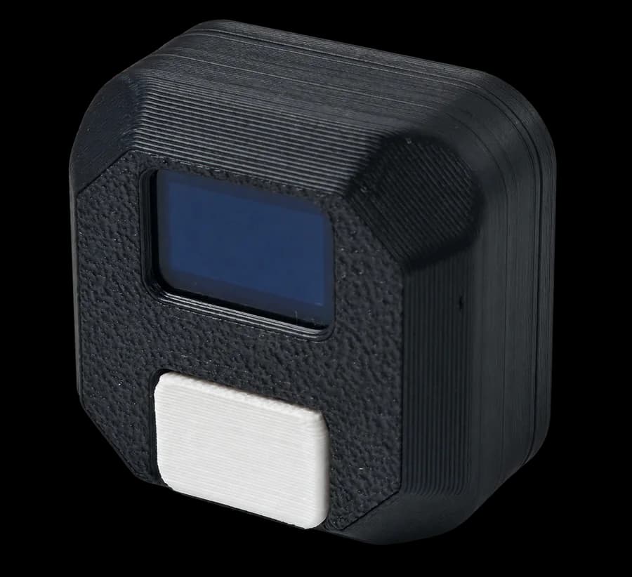
What Is a Motion Sensor
In earlier lessons, the robot measured travel with encoders and found a path with line sensors. Now we will add another source of information: the motion sensor.
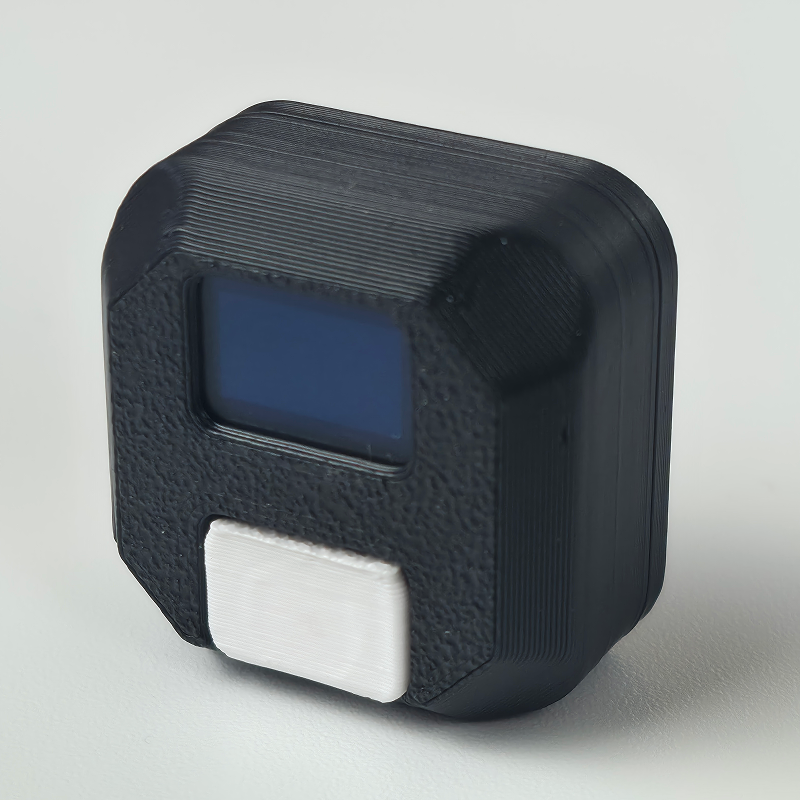
The motion sensor helps the robot understand its orientation: whether it turned, tilted forward, or leaned to one side. Inside the module are an accelerometer, a gyroscope, a dedicated controller, and an OLED display. The sensor controller processes the measurements and sends ready-to-use angles to Arduino.
This type of module is often called an IMU, or inertial measurement unit. Rotation around the vertical axis is especially useful on the field. With it, the robot can:
- turn through a chosen angle;
- hold its initial heading while driving straight;
- detect a heading error and correct it with the motors;
- repeat a route more accurately than with timed movement alone.
The motion sensor does not replace the encoders. Encoders measure wheel rotation, while the motion sensor measures the orientation of the whole robot. The movement functions in this lesson use both: the motion sensor controls heading and the encoders control travel distance.
Sensor Address
The current MotionSensor library and LittleRobot movement commands use address 0x60 by default. Check the module’s actual address with a scanner: a previously configured sensor may respond at a different address.
How to change the address: the I2C scanner and the address-change procedure are covered in Lesson 3, “Finding and changing an address”. For the motion sensor, use the Arduino IDE example:
File → Examples → Barigadam_MotionSensor → ChangeAddress.
For the assembled course robot, the recommended motion sensor address is:
0x60
The color-sensor library defaults to 0x40; different devices on the same bus need different addresses.
First find the real address with the scanner from Lesson 3. If the scanner reports 0x60, you can use the short Turn_Gyro() and Go_Gyro() calls with their default settings. If the sensor still responds at 0x40, either change its address or configure LittleRobot explicitly, as shown later in this lesson.
Yaw, Pitch, and Roll
The sensor reports three orientation angles:
Yaw— rotation around the vertical axis;Pitch— tilt forward or backward;Roll— tilt left or right.
Imagine the robot standing on a level field. When it turns in place, Yaw changes the most. Lifting the front changes Pitch; lifting one side changes Roll.
Field movement mainly uses Yaw. This is the value compared by Turn_Gyro() and Go_Gyro().
With the sensor mounted in the standard orientation, the sign of Yaw indicates turn direction:
- turning right increases the value, for example from
0°to+90°; - turning left decreases the value, for example from
0°to-90°.
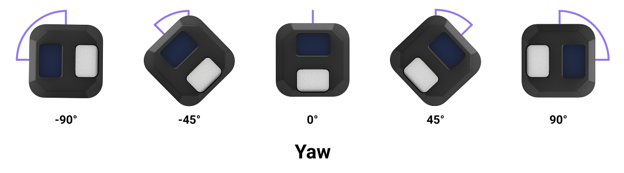
Verify this in Serial Monitor after assembly. If the signs change the other way around, check the sensor orientation on the chassis.
Sensor Libraries
Reading the sensor requires two libraries:
#include <Wire.h>
#include <Barigadam_MotionSensor.h>
Wire.h handles I2C communication. Barigadam_MotionSensor.h contains the module's angle-reading, reset, calibration, and configuration functions.
Programs that move the robot also include:
#include <LittleRobot.h>
This library provides ready-made turning and straight-driving functions that correct heading with Yaw.
Create a sensor object with the address found by the scanner:
BarigadamMotionSensor sensor(0x60);
If the scanner found a different address, replace 0x60 with that value.
Reading Angles
The getYaw(), getPitch(), and getRoll() Methods
Read each angle through the sensor object:
float yaw = sensor.getYaw();
float pitch = sensor.getPitch();
float roll = sensor.getRoll();
The methods return degrees as float values. Store the results in float variables, not int, to preserve tenths of a degree.
Test program:
#include <Wire.h>
#include <Barigadam_MotionSensor.h>

BarigadamMotionSensor sensor(0x60);

void setup() {
  Serial.begin(9600);
  Wire.begin();
  delay(20);
}

void loop() {
  float yaw = sensor.getYaw();
  float pitch = sensor.getPitch();
  float roll = sensor.getRoll();

  Serial.print("Yaw: ");
  Serial.print(yaw, 1);
  Serial.print("  Pitch: ");
  Serial.print(pitch, 1);
  Serial.print("  Roll: ");
  Serial.println(roll, 1);

  delay(100);
}
Upload the program and open Serial Monitor at 9600 baud. Turn the robot in place, then carefully tilt it forward and to one side. The readings should change smoothly and match the chassis movement.
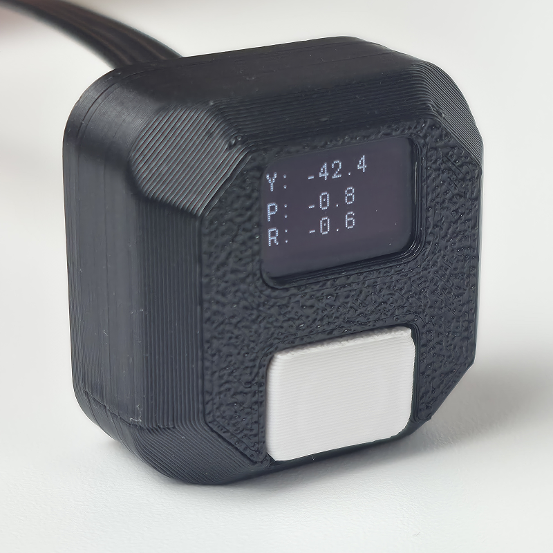
The current readings also appear on the sensor's OLED display when normal mode is enabled.
If Serial Monitor always shows zeros, check the address first. These methods also return 0 when the sensor does not answer, so zero does not always mean that the robot is level.
Reading All Three Angles Together
Three separate methods perform three I2C reads. readYPR() gets every angle in one transaction:
float yaw = 0;
float pitch = 0;
float roll = 0;

bool ok = sensor.readYPR(yaw, pitch, roll);
It returns true after receiving all data. On failure, it returns false and sets the outputs to zero, so a real 0° reading can be distinguished from a communication error.
Use readYPRRaw() when integer values in degrees multiplied by 10 are needed:
int16_t yaw10 = 0;
int16_t pitch10 = 0;
int16_t roll10 = 0;

bool ok = sensor.readYPRRaw(yaw10, pitch10, roll10);

float yaw = yaw10 / 10.0;
float pitch = pitch10 / 10.0;
float roll = roll10 / 10.0;
For example, 900 means 90.0 degrees and -450 means -45.0 degrees. The individual methods are convenient for one angle; readYPR() is better when all three axes are needed.
Zero Reset and Calibration
Zero reset and calibration are different operations.
A zero reset treats the current orientation as the starting orientation. Current Yaw, Pitch, and Roll become close to zero, but the sensor does not remeasure its internal gyroscope offset.
Calibration measures gyroscope offset. The sensor must remain completely still while calibration is running. The current orientation is also set to zero when calibration finishes.
The button on the module works as follows:
- one short press — reset the current angles to zero;
- two short presses — show the current address and mode on the OLED;
- one long press — run full calibration, then reset the angles to zero.
Before accurate movement:
- Place the robot on a level, stationary surface.
- Make sure the sensor is mounted firmly.
- Hold the button to run full calibration.
- Do not touch the robot until calibration finishes and the angles return to the display.
- Put the robot in its exact starting position and, if needed, short-press the button to reset zero.
Repeat calibration after a strong impact, a mounting change, visible angle drift at rest, or before a task that depends on especially accurate turns.
Reset and Calibration from Code
The sensor object provides a method for each action:
sensor.zeroReset()— zero reset;sensor.calibrate100()— quick calibration;sensor.calibrate500()— full calibration.
For example, this standalone sketch resets zero:
#include <Wire.h>
#include <Barigadam_MotionSensor.h>

BarigadamMotionSensor sensor(0x60);

void setup() {
  Serial.begin(9600);
  Wire.begin();
  delay(20);

  bool ok = sensor.zeroReset();

  if (ok) {
    Serial.println("Zero reset command sent");
  } else {
    Serial.println("I2C error: check address and wiring");
  }
}

void loop() {

}
For full calibration, call sensor.calibrate500(). Keep the robot still and wait for the OLED to show that calibration has finished. A true result confirms that the I2C command was transmitted, not that calibration itself has completed.
Sensor Modes
The module has three modes:
- mode
0— OLED off; I2C measurements continue; - mode
1— OLED shows angles and the button is enabled; - mode
2— OLED shows angles but button presses are ignored.
Mode 1 is the normal classroom mode. Mode 2 is useful in competition: an accidental press cannot reset zero or start calibration. The sensor stores its address and mode after power is removed.
Set the mode through the sensor object:
bool ok = sensor.setMode(1);
The method accepts 0, 1, or 2, sends one command, and returns true when the I2C write succeeds. Code after the call continues to run. A complete sketch is available under Barigadam_MotionSensor → ChangeMode.
Changing mode is not required for the regular lesson.
The library also supports heading-measurement correction. sensor.setCourseCorrection(value) applies a coefficient from 0.5 through 1.5, and sensor.saveCourseCorrection() stores it in the module. Use the included Barigadam_MotionSensor → CourseCorrection example for this setup.
Preparing the LittleRobot Library
Movement programs create a robot object:
LittleRobot robot;
Initialize it in setup():
robot.begin(true, true);
This function configures motors and encoders and starts I2C itself, so a program that calls robot.begin() does not need a separate Wire.begin().
If the Sensor Address Is 0x40
The short movement functions expect address 0x60. If the scanner found your sensor at 0x40, update the address in both settings groups:
const uint8_t MOTION_SENSOR = 0x40;

robot.Turn_Gyro_Settings.addr = MOTION_SENSOR;
robot.Go_Gyro_Settings.addr = MOTION_SENSOR;

robot.Turn_Gyro_Settings_Save();
robot.Go_Gyro_Settings_Save();
Run this after robot.begin() and before the first movement command.
Turning and driving with stopping enabled use MotorsHold(). It needs no I²C address because it stops using encoders. To call it separately, use robot.MotorsHold().
Short-form functions restore their settings to the saved values after each call. The ..._Settings_Save() calls above make the chosen address persist for later commands.
This block is not needed when the sensor is already configured at 0x60.
Turning with the Motion Sensor
In the encoder lesson we used robot.Rotate(), which estimates a turn from wheel rotation. If the wheels slip, the encoders still report movement even though the chassis turned through a smaller angle.
Turn_Gyro() controls the chassis angle using Yaw:
robot.Turn_Gyro(speed, angle);
Parameters:
speed— working turn-speed command on a0–100scale; near the target, the library automatically selects a final-alignment mode with its own limits;angle— change inYaw, in degrees, relative to the start of the command.
For example:
robot.Turn_Gyro(35, 90);
The robot remembers the current Yaw, adds 90 degrees, and runs the motors in opposite directions until the new heading is reached. The library performs precise braking at the end.
Use a negative angle to turn left:
robot.Turn_Gyro(35, -90);
With the standard assembly, a positive angle turns the robot right and a negative angle turns it left. Test both commands on a clear surface first.
Test program:
#include <Wire.h>
#include <Barigadam_MotionSensor.h>
#include <LittleRobot.h>

LittleRobot robot;

void setup() {
  Serial.begin(9600);
  robot.begin(true, true);

  robot.waitButtonPressRelease();

  robot.Turn_Gyro(35, 90);
}

void loop() {

}
Before pressing the button, place the robot where its wheels can turn freely. It should turn by about a right angle and stop.
Do not call Turn_Gyro(90) with one parameter. The current library requires two parameters: speed and angle.
Turn_Gyro() Settings
Accuracy parameters are stored in:
robot.Turn_Gyro_Settings
Available settings:
addr— sensor address, default0x60;restriction— fraction of working speed outside the final-alignment zone, default0.9;error_ok— allowed angle error, default0.9degree;more_power—0for normal final alignment (default),1for increased minimum effort near the target.
For example, increase the angle tolerance to 1.2 degrees: this is an experimental value, not a new default. The library calculates the slowdown zone itself. Both more_power modes use MotorStart. During the turn, the wheels are synchronized using encoders; the final MotorsHold does not correct Yaw.
robot.Turn_Gyro_Settings.error_ok = 1.2;
robot.Turn_Gyro(35, 90);
This change affects the next call only, then returns to the saved value. To make it persistent, call robot.Turn_Gyro_Settings_Save() before the first turn.
Speeds around 30–45 and the default settings are a good starting point. Excessive speed increases slip and overshoot, while very low speed may not start the motors.
Driving Straight While Holding Heading
Even with equal motor commands, the robot may drift because of motor differences, wheels, surface, weight distribution, or battery charge.
Go_Gyro() remembers the starting Yaw and adjusts left and right motor speeds to hold that heading:
robot.Go_Gyro(start_speed, working_speed,
              accel_degrees, cruise_degrees, decel_degrees);
Parameters:
start_speed— positive starting speed, no higher than the working speed;working_speed— speed of the cruising segment;accel_degrees— first segment, acceleration to working speed;cruise_degrees— second segment at working speed;decel_degrees— third segment, deceleration back to starting speed.
For example:
robot.Go_Gyro(20, 35, 100, 520, 100);
At the start, the library stores the current Yaw and resets both encoders. During movement it corrects heading using Yaw and additionally synchronizes the wheels using encoders. The command finishes when average encoder readings, accounting for direction, reach 100 + 520 + 100 = 720°. These are starting values for learning and need testing on the robot.
The second parameter is the working speed. Travel is the sum of the third, fourth, and fifth arguments: these are wheel degrees, not chassis angle, millimeters, or time. A zero-length segment is skipped, but total travel must be positive. Starting speed must be positive and no higher than working speed. Tune the travel for your robot. The current library has no two-argument form.
Driving Backward
Keep speed and distance positive and change direction with a setting:
robot.Go_Gyro_Settings.direction = -1;
robot.Go_Gyro(20, 35, 100, 520, 100);
1 means forward and -1 means backward. The setting applies to the next call and then returns to its saved value.
Go_Gyro() Settings
Straight-driving settings are stored in:
robot.Go_Gyro_Settings
It contains:
kp— response to current heading error, default5.0;kd— response to change in error, default50.0;stop— whether to brake automatically, default1;direction— direction1or-1;addr— motion sensor address, default0x60.
For example, explicitly set the standard gains, 5 and 50:
robot.Go_Gyro_Settings.kp = 5;
robot.Go_Gyro_Settings.kd = 50;
robot.Go_Gyro(20, 35, 100, 520, 100);
Change one value at a time and test on the same field section. Gains that are too large cause side-to-side oscillation; gains that are too small produce weak correction.
With stop = 1, the library performs a stop through MotorsHold using encoders. With stop = 0, the function finishes counting but the motors keep their latest commands. Use stop = 0 only when the next line immediately starts another movement or stops the motors.
Hands-On Practice
Build a route with two straight sections and one 90-degree turn. This program expects the motion sensor at address 0x60.
#include <Wire.h>
#include <Barigadam_MotionSensor.h>
#include <LittleRobot.h>

LittleRobot robot;

void setup() {
  Serial.begin(9600);
  robot.begin(true, true);

  robot.waitButtonPressRelease();

  robot.Go_Gyro(20, 35, 100, 520, 100);
  delay(400);

  robot.Turn_Gyro(35, 90);
  delay(400);

  robot.Go_Gyro(20, 35, 100, 520, 100);
}

void loop() {

}
Before starting, calibrate the sensor, place the robot at the starting pose, and reset zero. Clear the area around the robot, then press the Control Deck button.
The program runs in three steps:
robot.Go_Gyro(20, 35, 100, 520, 100)stores the initial heading and drives the first section.robot.Turn_Gyro(35, 90)turns the chassis90degrees relative to its current heading.- The second
robot.Go_Gyro(20, 35, 100, 520, 100)stores the new heading and holds it on the second section.
Run the route several times from the same starting point. Then try:
- changing
90to-90; - changing speed from
35to30or40; - calibrating the encoder value for a chosen section length;
- driving the second section backward with
Go_Gyro_Settings.direction = -1; - making a square with four straight sections and four turns.
A loop is convenient for the square:
for (int side = 0; side < 4; side++) {
  robot.Go_Gyro(20, 35, 100, 520, 100);
  delay(300);

  robot.Turn_Gyro(35, 90);
  delay(300);
}
If the robot does not return exactly to the start, measure straight-driving error and turn error separately. Do not change every setting at once: tune one straight section, then one turn, and only then test the full square.
Troubleshooting
Every Angle Is Zero
Check power, SDA, and SCL, then run the I2C scanner. The address in the program must match the scan result.
The Motors Start but Do Not Stop
Turn off power immediately. Usually the function cannot read the correct Yaw because of a wrong address or wiring. Make sure Turn_Gyro_Settings and Go_Gyro_Settings use the sensor's real address.
The Robot Turns the Wrong Way
Change the sign of the angle: use -90 instead of 90. Also check sensor orientation and verify motor direction with the standard program from Lesson 4.
The Robot Overshoots or Oscillates
Reduce turn speed, check sensor mounting and battery charge. Then check the error_ok tolerance and more_power alignment mode, changing one parameter at a time.
The Robot Drifts While Driving Straight
Recalibrate on a stationary surface, check the wheels, and make sure the sensor cannot wobble. Then tune kp and kd for Go_Gyro() one at a time.
The Angle Changes While the Robot Is Still
A small change is possible, but steady visible drift means calibration is needed. The robot and its surface must remain completely still during calibration.
The motion sensor improves route accuracy, but the result still depends on mechanics. A reliable program comes from checking address, calibration, speed, section length, and turn angle in that order.