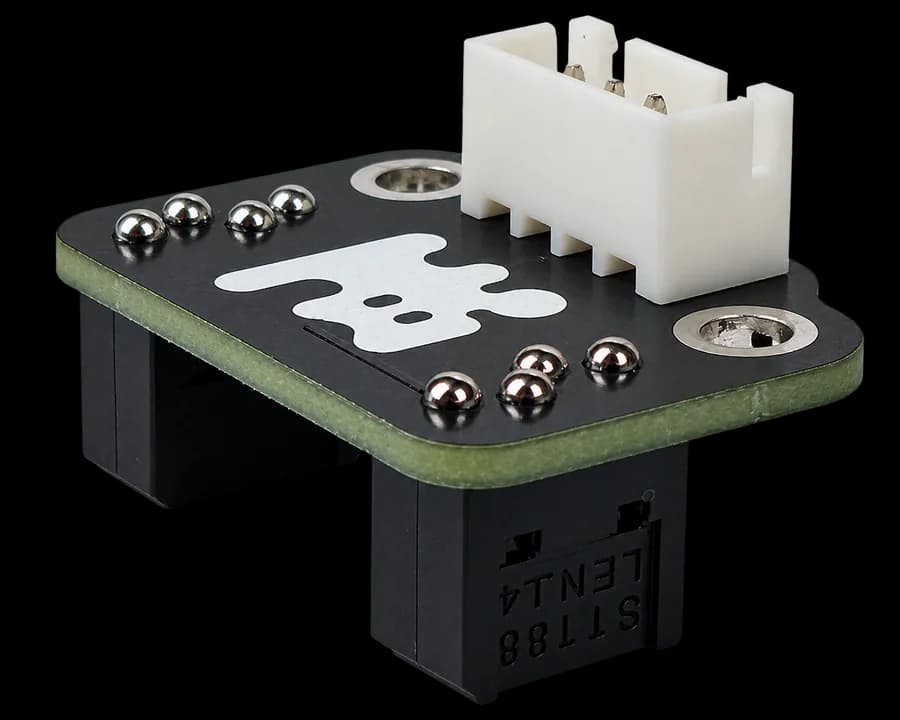
What is a line sensor
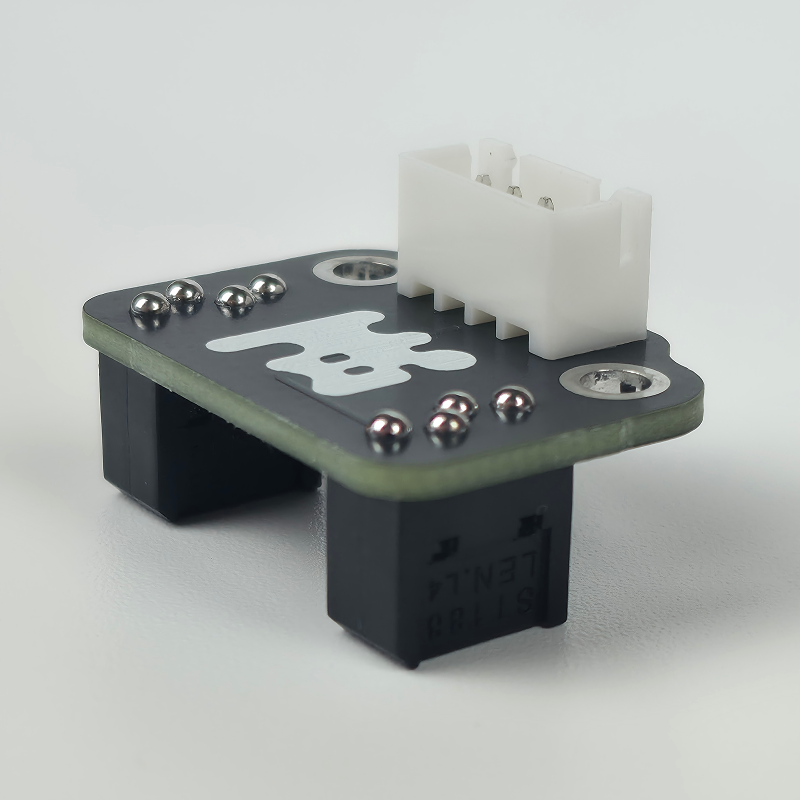
In the previous lessons, the robot learned how to move and use encoders. Now we will add a sensor that helps it orient itself on the field.
A line sensor determines whether the surface beneath it is dark or light. Thanks to this, the robot can find a line, follow it, and detect intersections.
The sensor does not recognize color the way a person does. It illuminates the surface and measures the amount of reflected light. A light surface usually reflects more light, and a dark surface reflects less. Arduino receives the measurement result as a number.
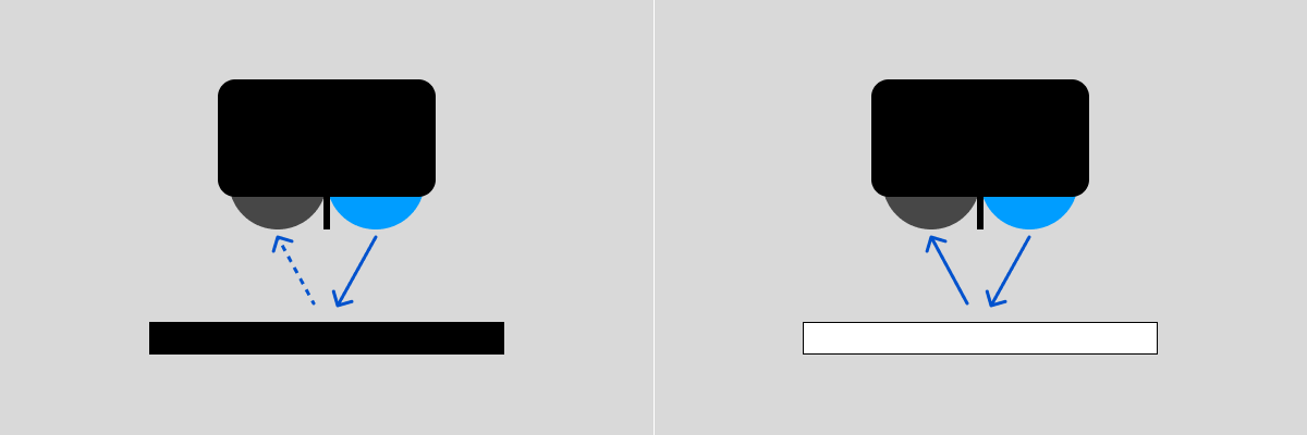
The Barigadam sensor can work with a dark line on a light background or a light line on a dark background. In this lesson, we use the standard option for LittleRobot functions: a black line on a white field.
The recommended distance from the sensor to the surface is about 5–30 mm. If the sensor is mounted too high, the difference between the line and the background may become too small.
Sensor placement and wiring
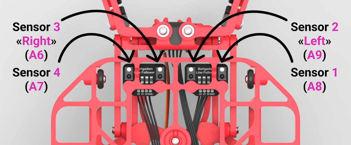
The Little Robot has two dual-channel modules installed. Each module has two sensitive zones, so the robot receives four separate readings in total.
In the LittleRobot library, they are numbered from 1 to 4:
- sensor
1—A8; - sensor
2, the left center sensor —A9; - sensor
3, the right center sensor —A6; - sensor
4—A7.
The names left and right refer to the robot's own sides. When you look at the robot from the front, they therefore appear mirrored in the diagram: sensor 2 is the robot's left sensor, while sensor 3 is its right sensor.
For line following, the default pair is the center sensors — 2 and 3. Sensors 1 and 4 are closer to the edges and, together with the center sensors, can be used to detect a wide line or an intersection.
Reading the sensor
Line sensors send a regular analog signal. That means you do not need a separate library to get readings — the standard Arduino command is enough:
analogRead(pin_number);
For example, the center sensors can be read like this:
int leftSensor = analogRead(A9);   // sensor 2
int rightSensor = analogRead(A6);  // sensor 3
The analogRead() command returns a number from 0 to 1023. This is the raw reading: Arduino has not yet determined whether the sensor is over the line or over the background.
Upload a program that prints readings from all four sensors:
void setup() {
  Serial.begin(9600);
}
void loop() {
  Serial.print("1: ");
  Serial.print(analogRead(A8));
  Serial.print("   2: ");
  Serial.print(analogRead(A9));
  Serial.print("   3: ");
  Serial.print(analogRead(A6));
  Serial.print("   4: ");
  Serial.println(analogRead(A7));
  delay(100);
}
Open Serial Monitor at 9600 baud and take two measurements:
- Place all sensors over the black line and write down four values.
- Place them over the white background and write down the values again.
For example, you might get results like these:
| Surface | Sensor 1 | Sensor 2 | Sensor 3 | Sensor 4 |
|---|---|---|---|---|
| Black line | 440 |
385 |
410 |
360 |
| White background | 959 |
950 |
959 |
939 |
Readings depend on sensor height, lighting, and the surface, so you need to get your own numbers for your robot.
How to detect the line from a value
The simplest way to tell the line apart from the background is to choose a threshold value between the readings on black and white surfaces.
For sensor 2 from the example:
int threshold = (385 + 950) / 2;
This gives a value of 667. Then you can run a check:
int value = analogRead(A9);
if (value < threshold) {
  Serial.println("Black line");
} else {
  Serial.println("White background");
}
Here the < sign is used because in our example the black surface gives a smaller number. If the readings on your field are reversed, the condition needs to be changed as well.
Different sensors may need different thresholds. So it is better to calculate a separate value for each one:
const int leftThreshold = (385 + 950) / 2;   // sensor 2
const int rightThreshold = (410 + 959) / 2;  // sensor 3
What is a motion controller
Now the robot can determine which of the center sensors is over the line. Based on these two checks, you can write a simple movement algorithm:
- line under the left sensor — turn left;
- line under the right sensor — turn right;
- sensors show the same surface — drive straight.
This algorithm is called a relay controller. It does not calculate the exact turning force. Instead, it chooses one of three preset actions: turn left, turn right, or keep driving straight.
In the previous lesson, we already controlled the motors with the LittleRobot library. Now we use sensor readings so the robot can choose its direction of movement on its own.
#include <LittleRobot.h>

LittleRobot robot;

const int LEFT_SENSOR = A9;   // sensor 2
const int RIGHT_SENSOR = A6;  // sensor 3

// change thresholds for your lighting
const int leftThreshold = 470;
const int rightThreshold = 620;

void setup() {
  robot.begin(true, true);

  robot.waitButtonPressRelease();
}

void loop() {
  bool lineLeft = analogRead(LEFT_SENSOR) < leftThreshold;
  bool lineRight = analogRead(RIGHT_SENSOR) < rightThreshold;

  if (lineLeft && !lineRight) {
    // Turn left
    robot.MotorPower(1, -10);
    robot.MotorPower(2, 40);
  } else if (lineRight && !lineLeft) {
    // Turn right
    robot.MotorPower(1, 40);
    robot.MotorPower(2, -10);
  } else {
    // Drive straight
    robot.MotorPower(1, 30);
    robot.MotorPower(2, 30);
  }
}
If the line is under the left sensor, the left wheel receives a small reverse power command of -10, and the right wheel receives forward power 40: the robot turns left. For the right sensor, the commands are swapped. When the readings agree, both motors receive 30. Thresholds 470 and 620 are examples for particular conditions; replace them with your measurements.
This controller is easy to understand, but the robot may move in jerks: the turning speed is always the same, no matter how far it has drifted. It also cannot tell apart two situations: the line is between the sensors, or the line is completely lost. In both cases, the center sensors may see white background.
Error
The previous controller only detected whether the line was present and always turned with the same force. To make movement smoother, the robot needs to know how much the readings of the two sensors differ.
For convenience, let us assume that the readings of both sensors are already scaled to a common range of 0–255:
0— black surface;255— white surface.
Consider a few situations:
| Left sensor | Right sensor | Difference |
|---|---|---|
200 |
200 |
0 |
80 |
220 |
-140 |
230 |
90 |
140 |
The difference between sensor readings is called error:
int error = leftValue - rightValue;
From the sign of the error, the robot determines the turning direction:
- a negative error — the line is closer to the left sensor;
- a positive error — the line is closer to the right sensor;
- an error near
0— the sensor readings are almost the same.
The farther the error is from zero, the more the robot has drifted from the line and the harder it needs to turn.
Now let us see how to get such values. Different sensors may give different readings on black and white surfaces. So before calculating the error, they need to be converted to the same scale. The map() function is used for this:
int leftRaw = analogRead(A9);
int rightRaw = analogRead(A6);

int leftValue = map(leftRaw, 385, 950, 0, 255);
int rightValue = map(rightRaw, 410, 959, 0, 255);
The map() function converts a number from one range to another.
In the line for the left sensor:
leftRaw— the current sensor reading;385and950— values on black and white surfaces;0and255— the bounds of the new scale.
If the left sensor returns 385, the function converts that reading to 0, and the value 950 to 255. All values in between are recalculated automatically. For example, a value around 667 becomes about 127.
For the right sensor, the values 410 and 959 are used in the same way. Replace these numbers with your own measurements.
After conversion, the result may be less than 0 or greater than 255. To keep it within the bounds of the new scale, use the constrain() function:
leftValue = constrain(leftValue, 0, 255);
rightValue = constrain(rightValue, 0, 255);
In the line for the left sensor:
leftValue— the value to check;0— the minimum allowed value;255— the maximum allowed value.
If the value is less than 0, the function returns 0. If it is greater than 255, the function returns 255. A value inside this range stays unchanged.
Proportional controller
In the relay controller, the robot chose one of three preset actions: drive straight, turn left, or turn right. The turning force always stayed the same.
A proportional controller works more smoothly. It does not use a preset turning force. Instead, it calculates the force each time from the sensor readings:
- The robot gets readings from the left and right sensors.
- It calculates the error — the difference between the readings.
- From the error, it determines the turning direction and force.
- It changes motor speeds and checks the sensors again.
These steps repeat constantly inside loop(). As the robot returns to the center of the line, the sensor readings even out, the error decreases, and the robot starts driving straighter.
The turning force is calculated from the error:
float correction = error * Kp;
In this case:
error— the error calculated from sensor readings;Kp— the coefficient that sets the robot's sensitivity;correction— the motor speed adjustment.
The coefficient Kp shows how strongly the robot should react to the error. For example, if the error is 50 and Kp is 0.1, the correction will be 5:
correction = 50 * 0.1;
If the error doubles, the correction doubles as well. That is why this controller is called proportional.
First, set the robot's normal driving speed:
const int baseSpeed = 35;
const float Kp = 0.1;
baseSpeed is the speed at which the robot moves when the error is zero. The correction is added to one motor's speed and subtracted from the other:
float leftSpeed = baseSpeed + correction;
float rightSpeed = baseSpeed - correction;
If the correction is positive, the left motor speeds up and the right motor slows down — the robot turns right. If the correction is negative, the right motor becomes faster and the robot turns left.
The main job of the controller is to constantly reduce the error and return the robot to the center of the line. Here is a simple proportional controller program:
#include <LittleRobot.h>

LittleRobot robot;

// Sensor pins
const int LEFT_SENSOR = A9;
const int RIGHT_SENSOR = A6;

// Sensor readings on black and white surfaces
const int blackLeft = 385;
const int whiteLeft = 950;
const int blackRight = 410;
const int whiteRight = 959;

const int baseSpeed = 35;  // normal driving speed
const float Kp = 0.1;      // controller sensitivity

void setup() {
  robot.begin(true, true);
}

void loop() {
  // Get raw sensor readings
  int leftRaw = analogRead(LEFT_SENSOR);
  int rightRaw = analogRead(RIGHT_SENSOR);

  // Convert readings to a 0–255 scale
  int leftValue = map(leftRaw, blackLeft, whiteLeft, 0, 255);
  int rightValue = map(rightRaw, blackRight, whiteRight, 0, 255);

  // Limit values to the scale bounds
  leftValue = constrain(leftValue, 0, 255);
  rightValue = constrain(rightValue, 0, 255);

  // Calculate the difference between sensors
  int error = leftValue - rightValue;

  // Calculate turning force
  float correction = error * Kp;

  // Change motor speeds
  float leftSpeed = baseSpeed + correction;
  float rightSpeed = baseSpeed - correction;

  // Send calculated speeds to the motors
  robot.MotorPower(1, leftSpeed);
  robot.MotorPower(2, rightSpeed);
}
Replace the numbers 385, 950, 410, and 959 with your own sensor readings.
The coefficient Kp is tuned experimentally. If it is too small, the robot will react weakly to the line and may drive off it. If it is too large, the robot will turn sharply and weave from side to side.
PD controller
The proportional controller only takes the current error into account. Because of this, the robot may reduce the turn too late, cross the center of the line, and start drifting the other way. As a result, it will weave.
To make movement calmer, you need to consider not only the error itself, but also how it changed since the last measurement.
To do this, subtract the previous error from the current one:
int errorChange = error - previousError;
In this case:
error— the current error;previousError— the error from the previous pass throughloop();errorChange— the change in error.
For example, if the previous error was 20 and the current one became 60, the error change will be:
errorChange = 60 - 20;
The result is 40. This means the error is increasing quickly and the robot is continuing to drift from the line.
If the previous error was 60 and the current one became 20, the result is -40. That means the error is decreasing and the robot is returning to the center of the line.
In a PD controller, the correction has two parts:
float correction = error * Kp + errorChange * Kd;
In this case:
error * Kpaccounts for the robot's current position;errorChange * Kdaccounts for the change in error;Kdsets how strongly the error change affects the turn.
When the error increases quickly, the second part strengthens the turn. When the robot quickly returns to the center of the line, it reduces the correction and helps the robot avoid overshooting the line.
For the controller to compare errors, the variable previousError is created before setup():
int previousError = 0;
This lets it keep its value between passes through loop().
Here is a full PD controller program:
#include <LittleRobot.h>

LittleRobot robot;

// Sensor pins
const int LEFT_SENSOR = A9;
const int RIGHT_SENSOR = A6;

// Sensor readings on black and white surfaces
const int blackLeft = 385;
const int whiteLeft = 950;
const int blackRight = 410;
const int whiteRight = 959;

// Controller settings
const int baseSpeed = 35;
const float Kp = 0.1;
const float Kd = 0.2;

// Error from the previous loop() pass
int previousError = 0;

void setup() {
  robot.begin(true, true);
}

void loop() {
  // Get raw sensor readings
  int leftRaw = analogRead(LEFT_SENSOR);
  int rightRaw = analogRead(RIGHT_SENSOR);

  // Convert readings to a 0–255 scale
  int leftValue = map(leftRaw, blackLeft, whiteLeft, 0, 255);
  int rightValue = map(rightRaw, blackRight, whiteRight, 0, 255);

  // Limit readings to the scale bounds
  leftValue = constrain(leftValue, 0, 255);
  rightValue = constrain(rightValue, 0, 255);

  // Calculate the current error
  int error = leftValue - rightValue;

  // Compare it with the previous error
  int errorChange = error - previousError;

  // Calculate the PD correction
  float correction = error * Kp + errorChange * Kd;

  // Calculate motor speeds
  float leftSpeed = baseSpeed + correction;
  float rightSpeed = baseSpeed - correction;

  // Limit speeds to values from 0 to 100
  leftSpeed = constrain(leftSpeed, 0, 100);
  rightSpeed = constrain(rightSpeed, 0, 100);

  // Send calculated speeds to the motors
  robot.MotorPower(1, leftSpeed);
  robot.MotorPower(2, rightSpeed);

  // Save the error for the next pass
  previousError = error;

  // Make the interval between measurements more stable
  delay(2);
}
Replace the numbers 385, 950, 410, and 959 with your own sensor readings.
The coefficients Kp and Kd are tuned experimentally. First set Kd = 0 and tune Kp until the robot confidently returns to the line. Then gradually increase Kd until the movement becomes calmer.
If Kd is too small, the robot will keep weaving. If it is too large, the movement may become sharp and jerky.
Using the LittleRobot library
We read analog inputs ourselves, detected the line, calibrated the sensors, calculated the error, and changed motor speeds. Now let us look at functions from the LittleRobot.h library that simplify these steps.
At the start of the program, include the library and create a robot object:
#include <LittleRobot.h>
LittleRobot robot;
In setup(), perform the initial robot setup:
robot.begin(true, true);
Getting raw readings
To get a raw reading, use:
robot.readLightRaw(sensor_number);
Put a sensor number from 1 to 4 inside the parentheses. For example:
int value = robot.readLightRaw(2);
In this case:
2— the sensor number;value— the variable that stores its reading.
The function returns a regular value from 0 to 1023. It works the same way as analogRead(), but takes a sensor number instead of a pin. The library already knows that sensor 2 is connected to pin A9.
Sensor calibration
For the library to convert readings correctly, it needs the measured values on black and white surfaces.
Use this function:
robot.setLightCalibration(
  black1, black2, black3, black4,
  white1, white2, white3, white4
);
First pass four black readings, then four white readings, both in sensor order 1, 2, 3, 4: A8, A9, A6, A7. Follow sensor numbering, not ascending pin numbers.
For the measurements from our example, the function is written like this:
robot.setLightCalibration(
  440, 385, 410, 360,
  959, 950, 959, 939
);
Here:
440, 385, 410, 360— readings of sensors1–4on the black line;959, 950, 959, 939— readings of sensors1–4on the white background.
Call this function in setup() after starting the robot:
void setup() {
  robot.begin(true, true);

  robot.setLightCalibration(
    440, 385, 410, 360,
    959, 950, 959, 939
  );
}
Replace these numbers with your own measurements.
Getting a processed reading
After calibration, you can use:
robot.readLight(sensor_number);
For example:
float value = robot.readLight(2);
The library gets the raw reading on its own, converts it to a 0–255 scale, and limits it to that range. Inside, it performs the same steps we wrote earlier with analogRead(), map(), and constrain().
After proper calibration:
- a value near
0corresponds to a black surface; - a value near
255corresponds to a white surface.
So to get a prepared reading, one function call is enough:
float leftValue = robot.readLight(2);
float rightValue = robot.readLight(3);
Built-in PD controller
The LittleRobot library already includes a built-in PD controller that lets the robot follow a line for a set distance:
robot.PD_Enc(speed, distance, Kp, Kd);
Here is an example:
robot.PD_Enc(35, 720, 0.4, 2.0);
In this case:
35— the main driving speed on a scale from0to100;720— distance based on the average rotation angle of both wheels;0.4— theKpcoefficient;2.0— theKdcoefficient.
While moving, the function reads sensors 2 and 3, calculates the error, and changes motor speeds. At the same time, it tracks the encoders and stops the robot when the set distance is traveled.
The value 720 corresponds to about two wheel rotations. This is not a distance in millimeters. The actual distance depends on wheel diameter.
At the start, the function performs initial line alignment. By default, this uses the first 150° and is included in the total distance. So the distance value should be set greater than 150.
The function fills in the remaining settings automatically: it uses sensors 2 and 3, performs initial alignment, and stops the motors at the end.
Example program:
#include <LittleRobot.h>

LittleRobot robot;

void setup() {
  robot.begin(true, true);

  // Set your own calibration values
  robot.setLightCalibration(
    440, 385, 410, 360,
    959, 950, 959, 939
  );

  // Wait for a button press and release
  robot.waitButtonPressRelease();

  // Follow the line for about two wheel rotations
  robot.PD_Enc(35, 720, 0.4, 2.0);
}

void loop() {

}
Place the robot on the line and run the program. The coefficients for the built-in function are tuned separately: values from your own controller may not work for it. First set Kd = 0 and tune Kp, then gradually increase Kd until the movement becomes calmer.
Driving to an intersection
To follow a line until an intersection, use:
robot.PD_Cross(speed, minimum_distance, Kp, Kd);
Here is an example:
robot.PD_Cross(35, 200, 0.4, 2.0);
In this case:
35— the main driving speed;200— the minimum distance based on the average encoder value;0.4— theKpcoefficient;2.0— theKdcoefficient.
The function guides the robot along the line and checks for an intersection at the same time. The robot stops when both conditions are met:
- The average encoder value reaches
200°. - The required sensors detect a black line at that moment.
The parameter 200 sets not the exact distance, but the minimum distance before a possible stop. If no intersection is found after that distance, the robot keeps moving.
By default, all four sensors must detect the intersection at the same time. The processed reading of each one must be less than 150.
An intersection found before the minimum distance is not remembered. The robot must detect a suitable intersection after passing the set value.
If the required intersection is not present or the sensors are calibrated incorrectly, the robot will keep moving and the program will not move to the next line.
Additional movement settings
Usually, four main parameters are enough to start movement:
robot.PD_Enc(35, 720, 0.4, 2.0);
Additional settings are needed only when you want to change the default behavior of the function. Write them before starting it:
robot.PD_Enc_Settings.sensors = 12;
robot.PD_Enc(35, 720, 0.4, 2.0);
The first line changes the setting, and the second starts movement with the new value.
Choosing line sensors
By default, the center sensors 2 and 3 are used for movement:
robot.PD_Enc_Settings.sensors = 23;
You can choose a different pair:
// Sensors 1 and 2
robot.PD_Enc_Settings.sensors = 12;

// Or sensors 3 and 4
robot.PD_Enc_Settings.sensors = 34;
Only the options 12, 23, and 34 are supported.
For the intersection function, the setting is written through PD_Cross_Settings:
robot.PD_Cross_Settings.sensors = 23;
robot.PD_Cross(35, 200, 0.4, 2.0);
This setting determines which two sensors the robot uses to follow the line.
Initial alignment
By default, the first 150° of movement are used for initial line alignment.
You can change the length of this section like this:
robot.PD_Enc_Settings.degrees_align = 100;
robot.PD_Enc(35, 720, 0.4, 2.0);
To disable initial alignment completely, set the value to 0:
robot.PD_Enc_Settings.degrees_align = 0;
robot.PD_Enc(35, 720, 0.4, 2.0);
For PD_Cross(), use the corresponding setting:
robot.PD_Cross_Settings.degrees_align = 0;
Choosing intersection sensors
The PD_Cross() function has a separate setting called go_to. It determines which sensors must detect a black line at the same time for the robot to stop.
By default, all four sensors are used:
robot.PD_Cross_Settings.go_to = 1234;
For example, to stop using sensors 1 and 2, write:
robot.PD_Cross_Settings.go_to = 12;
robot.PD_Cross(35, 200, 0.4, 2.0);
For go_to, choose any nonempty combination of distinct digits from 1 to 4 in any order, such as 1, 14, 23, or 4312. 14 and 41 are equivalent. All selected sensors must simultaneously read below the threshold; other sensors are ignored.
Zero, negative numbers, repeated digits, and digits outside 1–4 are invalid. With an invalid go_to, PD_Cross brakes and returns without starting the drive.
Do not confuse the two settings:
sensorssets the pair of sensors the robot uses to follow the line;go_tosets the sensors the robot uses to detect an intersection.
After a short call the library restores saved settings. Until settings have been saved, these match the defaults. To reuse a selected setting, save it before movement:
robot.PD_Cross_Settings.go_to = 14;
robot.PD_Cross_Settings_Save();
PD_Enc has the equivalent PD_Enc_Settings_Save() method. This mechanism does not reset sensor calibration.
Intersection threshold
robot.PD_Cross_Settings.go_to = 14;
robot.PD_Cross_Settings.threshold = 130;
robot.PD_Cross(35, 200, 0.4, 2.0);
The default is threshold = 150; 130 is an experimental value. The comparison is strict: a reading must be below the threshold. robot.Intersection_Check(14, 130) returns 1 or 0, checking sensors without starting movement. The minimum travel requirement in PD_Cross still applies: an intersection detected too early is not remembered.
Choosing the motor mode
robot.PD_Enc_Settings.more_power = 0;
robot.PD_Enc(20, 300, 0.3, 2.0);
The default more_power = 1 uses MotorPower; 0 uses the new MotorStart. This applies during alignment and the main segment. PD_Cross has the same field. It selects how the driver is controlled, rather than simply increasing the numerical speed.
Practical part
Let us build a program in which the robot first drives a set distance along the line, then continues until it reaches an intersection.
Before running it, replace the calibration values with your own measurements.
#include <LittleRobot.h>

LittleRobot robot;

void setup() {
  // Start the robot
  robot.begin(true, true);

  // Set black line and white background values (change to your own)
  robot.setLightCalibration(
    440, 385, 410, 360,
    959, 950, 959, 939
  );

  // Wait for a button press and release
  robot.waitButtonPressRelease();

  // Drive the set distance along the line
  robot.PD_Enc(35, 720, 0.4, 2.0);

  delay(500);

  // All four sensors must see the intersection
  robot.PD_Cross_Settings.go_to = 1234;

  // Drive to the intersection
  robot.PD_Cross(35, 200, 0.4, 2.0);
}

void loop() {

}
After you press the button, the program will do the following:
- The robot will drive along the line for
720°. - It will stop for
500milliseconds. - It will continue moving along the line.
- It will drive at least
200°. - It will stop when all four sensors detect an intersection.
Test the program step by step. First leave only the PD_Enc() function and make sure the robot follows the line confidently. Then add the go_to setting and the PD_Cross() function.
If the robot returns to the line weakly, gradually increase Kp. If it weaves strongly, decrease Kp and gradually increase Kd.
Make sure there is a suitable intersection on the track. If the robot does not detect it, the PD_Cross() function will keep moving and the program will not finish.