What is an encoder
In the previous lesson, we controlled the motors by time: we started the motors, waited for the needed number of milliseconds with delay(), and then stopped the robot. This method is simple, but not very precise.
If the robot drives for one second, that does not always mean it will travel the same distance. Battery charge, field surface, motor speed, and even a little wheel friction all affect movement.
To make movement more accurate, encoders are used.
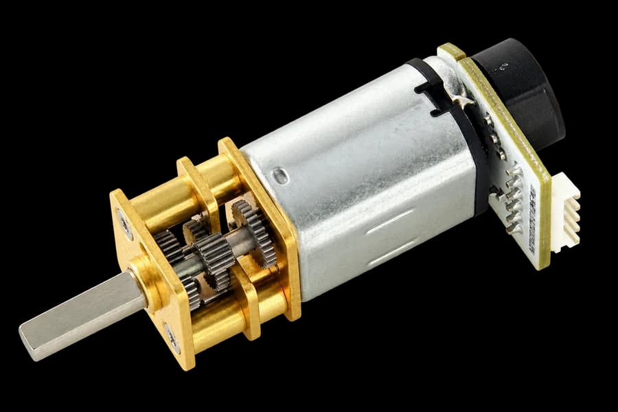
An encoder is a sensor that helps determine how the motor is rotating. It tracks shaft rotation and sends that data to the control board. Thanks to this, the robot can move not just for "about one second", but by a chosen amount linked to wheel rotation.
Encoder design and connection
The encoder is mounted on the back of the motor and rotates with its shaft. A motor with an encoder uses one six-pin connector that combines two different parts: the motor power leads and the contacts of the encoder board.
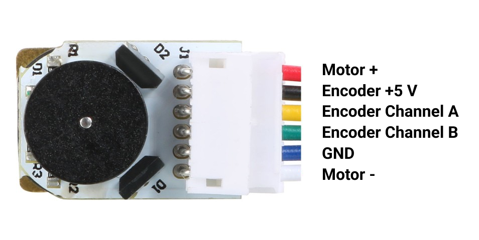
The connector has these contacts:
Motor +andMotor −— the two motor power leads. Through them the driver supplies power and changes rotation direction (for motor1 —M3andM4, for motor2 —M1andM2);5 VandGND— power for the encoder board;Channel AandChannel B— the two encoder signal outputs Arduino uses to detect shaft rotation.
In the standard assembly, the encoder signal lines are connected as follows:
- motor1 encoder — to pins
D19andD3; - motor2 encoder — to pins
D18andD2.
Even though all six wires are in one connector, the motor leads and the encoder leads serve different purposes. Motor + and Motor − connect to the motor driver, while the encoder power and signal channels connect to the control board.
It is important not to mix up encoder power with the motor power leads. Applying voltage to the wrong contacts can cause incorrect operation or damage the board.
How channels A and B work
When the shaft rotates, the encoder produces pulse sequences on channels A and B. These signals are slightly shifted relative to each other. From the number of pulses the library determines how far the shaft turned, and from which channel changed first — the direction of rotation.
That is why an encoder needs two signal channels. One channel could count rotation, but two channels also make it possible to determine direction.
Encoder readings
While rotating, the encoder creates pulses, and the library counts them. These pulses can be read as a raw count or converted into shaft rotation in degrees.
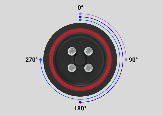
By default the library uses 1415 counts per full revolution. So about 360 encoder degrees correspond to one turn of the motor output shaft and the wheel mounted on it, and 720 degrees correspond to two turns.
It is important not to confuse these values with the turning angle of the whole robot. For example, encoder value 360 means one wheel revolution, not a 360-degree robot spin. Travel distance depends on wheel diameter, and the robot's turning angle also depends on the distance between the wheels.
Setting encoder direction
As before, at the start of the program you need to include the LittleRobot.h library, create a robot object, and run initialization:
#include <LittleRobot.h>

LittleRobot robot;

void setup() {
  robot.begin(true, true);
}
In the previous lesson we used this function as the required robot setup. Now let's look at its parameters in more detail.
The full form is:
robot.begin(encoder_1_invert, encoder_2_invert);
The first parameter applies to the motor1 encoder, and the second to the motor2 encoder:
true— the library flips the sign of the selected encoder readings;false— the readings are used without changing count direction.
These parameters do not change motor rotation direction. They only affect whether encoder values increase or decrease as the wheels turn. This setup is needed because the left and right motors are mounted mirrored, and the encoders themselves may be wired with different count directions.
For example:
robot.begin(true, false);
In this case the first encoder's count direction is inverted, and the second stays unchanged.
For the standard Little Robot assembly, use:
robot.begin(true, true);
If during a check one encoder changes in the opposite direction from what you expect, change only that parameter from true to false or the other way around. Then check the readings again in Serial Monitor.
How to read an encoder value
Before using ready-made movement commands, it is useful to see what values the encoders send.
To get raw counts without converting to degrees, use:
robot.getCounts(motor_number);
For most learning programs it is more convenient to get the result directly in degrees:
robot.getDegrees(motor_number);
Both functions return a value, so you need to store the result in a variable or print it to Serial Monitor right away:
float leftEncoder = robot.getDegrees(1);
float rightEncoder = robot.getDegrees(2);
Use the float type because the result may include a fractional part.
To start a new measurement from zero, reset one encoder or both:
robot.resetEncoder(1);  // reset one encoder
robot.resetAllEncoders();  // reset both encoders
The library also has:
robot.setCPR(1415);
It sets the number of encoder counts per revolution and affects the conversion from counts to degrees. The standard assembly already uses 1415, so you usually do not need to change it.
Let's write a small program to view encoder values, using the motor movement we already studied.
#include <LittleRobot.h>

LittleRobot robot;

void setup() {
  Serial.begin(9600);
  robot.begin(true, true);

  robot.waitButtonPressRelease();

  robot.resetAllEncoders();

  robot.MotorPower(1, 30);
  robot.MotorPower(2, 30);
}

void loop() {
  float leftEncoder = robot.getDegrees(1);
  float rightEncoder = robot.getDegrees(2);

  Serial.print("Left: ");
  Serial.print(leftEncoder);
  Serial.print("  Right: ");
  Serial.println(rightEncoder);

  delay(200);
}
After uploading the program, open Serial Monitor and press the button on the robot. When the motors start turning, the encoder values should change.
If a value does not change, check the encoder wiring and robot power. If a value changes in the opposite direction, that is not always an error: the counting direction depends on wiring and robot initialization settings.
Function settings
Some LittleRobot library functions have extra settings. They are set on a separate line before calling the function:
robot.FunctionSettings.setting_name = value;
robot.Function(...);
The first line names the settings group for the function, then after a dot the setting name and the new value. The second line calls the function itself. The setting must be written before the function call.
What a specific setting does and which values it accepts is explained next to the matching function. Settings are written before the movement command you want to change.
Straight movement by encoders
To move with both motors, use:
robot.MotorsMoveSync(speed_0, speed, enc_1, enc_2, enc_3);
The function itself resets both encoder readings, starts the motors, and continuously compares left and right wheel rotation. If one wheel begins to lead the other, the library slightly adjusts motor speeds so the robot drives more evenly.
Function parameters:
speed_0— speed at the beginning of movement;speed— speed the robot gradually reaches;enc_1— how many encoder degrees the acceleration lasts;enc_2— how many extra degrees the robot travels after acceleration at the main speed.
The fifth parameter, enc_3, sets the deceleration segment back to the starting speed. Movement has three sequential segments; total travel is enc_1 + enc_2 + enc_3. These are path segments, not different motors. If the final argument is omitted, enc_3 = 0, so deceleration is skipped.
For example:
robot.MotorsMoveSync(20, 50, 80, 350);
The robot starts at speed 20, over the first 80 encoder degrees smoothly accelerates to 50, then travels another 350 degrees at the main speed. When finished, the function stops the motors by default.
A starting speed around 15–30 is useful: too little power may not start the motor. A zero acceleration segment is skipped. For the examples, choose a positive starting speed no higher than the working speed, and a positive total distance.
The four-argument call above is still valid. Add deceleration while keeping the total travel at 430° instead of 80 + 350:
robot.MotorsMoveSync(20, 50, 80, 270, 80);
Straight movement settings
You can change MotorsMoveSync() behavior before calling it through this settings group:
robot.MotorsMoveSync_Settings
It has two parameters:
direction— movement direction;stop— whether to stop the motors after the command finishes.
For backward movement, use the direction setting:
robot.MotorsMoveSync_Settings.direction = -1;
robot.MotorsMoveSync(20, 50, 80, 350);
Value 1 means forward, and -1 means backward. The speeds stay positive.
By default the robot stops after the movement finishes because stop is 1. To keep the motors running after the command, set it to 0:
robot.MotorsMoveSync_Settings.stop = 0;
In simple terms, stop controls whether the robot should automatically stop after the function reaches the chosen encoder value.
- With
stop = 1, the function finishes the movement and stops the motors. Only then does the program continue to the next line. - With
stop = 0, the function finishes counting encoders but does not turn the motors off. They keep rotating at the last set speed until another command changes their behavior.
For example, stop = 0 is useful when after one segment the robot should immediately continue to the next without a short stop:
robot.MotorsMoveSync_Settings.stop = 0;
robot.MotorsMoveSync(20, 50, 80, 350);

// motors are still rotating
robot.MotorsMoveSync(20, 40, 60, 200);
robot.MotorsMoveSync(20, 50, 80, 350);
In this case the function ends, but the motors keep rotating at the last speed. The next command should change their speed or stop the robot. Use stop = 0 carefully.
Spot turn by encoders
For a spot turn, use:
robot.Rotate(speed_0, speed, enc_1, enc_2, enc_3);
While it runs, the motors rotate in opposite directions. The robot turns in place, and the library compares both encoder readings and tries to keep wheel rotation even.
The parameters work the same way as in MotorsMoveSync():
speed_0— speed at the beginning of the turn;speed— speed after acceleration;enc_1— the smooth acceleration segment;enc_2— extra wheel rotation at working speed after acceleration;enc_3— deceleration back to starting speed, default0.
For example:
robot.Rotate(20, 45, 80, 300);
The short example omits enc_3: deceleration is skipped and total wheel travel is 80 + 300 = 380°. This is not the chassis heading angle. Add the third segment without changing that total:
robot.Rotate(20, 45, 80, 220, 80);
With yaw_mode = 0, tune the wheel travel experimentally for a chassis turn of about 90 or 180 degrees. It depends on wheel diameter, wheel spacing, and surface grip.
Spot turn settings
Before calling Rotate(), you can change this settings group:
robot.Rotate_Settings
It has four parameters:
clockwise— turn direction;stop— whether to stop the motors when finished;to_line— whether to continue turning until a line is detected;yaw_mode— whether to specify an approximate chassis angle instead of wheel travel, default0.
By default clockwise is 1, so the robot turns clockwise — to the right when viewed from above. In that turn the left wheel rotates forward and the right wheel rotates backward.
To turn the other way — counterclockwise, to the left — set -1 before the function:
robot.Rotate_Settings.clockwise = -1;
robot.Rotate(20, 45, 80, 300);
The stop setting works the same as for straight movement:
robot.Rotate_Settings.stop = 0;
With value 0, the motors are not stopped when the function finishes.
The to_line setting is used when after the main turn the robot should keep rotating until it finds a line:
robot.Rotate_Settings.to_line = 1;
robot.Rotate(20, 45, 80, 300);
To find the line, the function uses the line sensors. For now it is enough to know what this parameter does — working with the line is covered in more detail in the next lesson.
Approximate chassis angle
robot.Rotate_Settings.yaw_mode = 1;
robot.Rotate(20, 45, 90);
Here the third argument specifies an approximate chassis angle. The library converts it to wheel rotation using its built-in geometry and divides the path into acceleration, cruising, and deceleration. Supplied enc_2 and enc_3 values are ignored. The gyroscope is not read; check accuracy on the robot. Set direction with clockwise = 1 or -1, not the angle’s sign.
By default yaw_mode = 0, so the arguments specify wheel degrees. To explicitly return to this mode, set robot.Rotate_Settings.yaw_mode = 0; before the next call.
One-wheel turn
Sometimes you need to keep one wheel still and turn with the other. For that, use:
robot.Turn_One(motor, speed_0, speed, enc_1, enc_2, enc_3);
For example:
robot.Turn_One(1, 20, 40, 60, 200);
In this example motor2 stays still, and motor1 first accelerates over 60 degrees, then travels another 200 degrees at main speed 40.
The first argument selects the motor; the next five are starting speed, working speed, and the three path segments, as in MotorsMoveSync. The short example above uses enc_3 = 0. This version adds deceleration and keeps the selected wheel’s travel at 260°:
robot.Turn_One(1, 20, 40, 60, 140, 60);
One-wheel turn settings
For Turn_One(), use this group:
robot.Turn_One_Settings
It has two parameters:
direction— rotation direction of the selected motor;stop— whether to stop it when the command finishes.
To change direction:
robot.Turn_One_Settings.direction = -1;
robot.Turn_One(1, 20, 40, 60, 200);
To leave the selected motor running after the function finishes:
robot.Turn_One_Settings.stop = 0;
By default direction is 1 and stop is 1.
A setting must be written before calling the matching function:
robot.MotorsMoveSync_Settings.direction = -1;
robot.MotorsMoveSync(20, 50, 80, 350);
So the next command will use the normal direction again:
robot.MotorsMoveSync(20, 50, 80, 350);
This is convenient when you need to change a parameter for only one command.
If the new value should be used permanently, you can save it:
robot.MotorsMoveSync_Settings.direction = -1;
robot.MotorsMoveSync_Settings_Save();
Now after each MotorsMoveSync() call the setting will return not to the original value, but to the saved -1.
Similar functions exist for the other groups:
robot.Rotate_Settings_Save();
robot.Turn_One_Settings_Save();
robot.MotorsHold_Settings_Save();
To save all current library settings at once:
robot.AllSettings_Save();
To restore a specific group to previously saved values:
robot.resetMotorsMoveSync_Settings();
robot.resetRotate_Settings();
robot.resetTurn_One_Settings();
And this command:
robot.resetAllSettings();
restores all settings groups to their saved values. It does not necessarily restore factory defaults if settings were earlier saved with ..._Settings_Save() functions.
Motor stop settings
With stop = 1, MotorsMoveSync() and Rotate() finish through MotorsHold(). It corrects wheel position using encoders and leaves electrical braking applied after stabilization. This stop does not need a motion sensor.
robot.MotorsHold_Settings.degree_error = 1.0;
robot.MotorsHold_Settings.degree_time = 100;
robot.MotorsMoveSync(20, 50, 80, 350);
1.0 degree is the allowed encoder error, and 100 ms is the stabilization confirmation time. These are the current defaults. MotorsHold runs until stabilization and then returns: it does not continue an endless background PD controller afterward. To reuse your settings, call robot.MotorsHold_Settings_Save() after setting them and before movement.
MotorsStop() still exists: it uses reverse thrust and the ms_1/ms_2 intervals, but those intervals no longer configure the final stop of MotorsMoveSync or Rotate. The line functions PD_Enc and PD_Cross still use MotorsStop. When stopping is enabled, Turn_One() ends with MotorStop(motor), not MotorsHold.
Practical part
Now let's build a program in which the robot drives forward, turns about 180 degrees, and drives back.
#include <LittleRobot.h>

LittleRobot robot;

void setup() {
  robot.begin(true, true);

  robot.waitButtonPressRelease();

  robot.MotorsMoveSync(20, 50, 80, 350);
  delay(500);

  robot.Rotate(20, 45, 80, 650);
  delay(500);

  robot.MotorsMoveSync(20, 50, 80, 350);
}

void loop() {

}
First MotorsMoveSync() smoothly accelerates both motors and synchronizes wheel rotation. Then Rotate() runs the wheels in opposite directions and performs the turn. After that the robot travels the same encoder value again and should roughly return along the same line.
The value 650 in Rotate() is not a 180-degree heading. It is the extra wheel rotation after the acceleration segment. Check it on your robot and increase or decrease it if needed.
Even when using encoders, the robot may drift a little. That is normal.
Possible reasons include:
- the wheels slip a little;
- the field surface is uneven;
- the batteries are low;
- the values need careful tuning.
Encoders help make movement more accurate, but they do not fix every physical error. That is why in robotics you often need to test movement on the field and tune the values.
Try changing the values in the program yourself and see how the robot's behavior changes. You can change the travel length in MotorsMoveSync(), the fourth parameter of Rotate(), or the motor speeds.
After that, try improving the program so the robot drives in a square. To do this, it should perform two actions four times: drive straight and turn by about 90 degrees. To avoid writing the same commands several times, use a for loop. It will help repeat the movement and turn four times in a row.