What are motors
In the previous lesson, we looked at the Control Deck and the main connectors. Now let's move on to one of the robot's main actuators: motors.
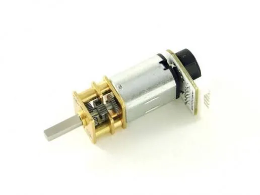
Motors are needed to move the robot. They rotate the wheels, and the Control Deck defines when the motors should turn on, which direction they should rotate, and what speed they should use.
The Little Robot uses two main motors: left and right. If both motors rotate the same way, the robot drives straight. If one motor rotates faster than the other, the robot starts turning.
Motor Driver
A motor cannot simply be connected directly to an Arduino port. A regular port can send a control signal, but it is not designed to power a motor. For this, a Motor Driver is used.
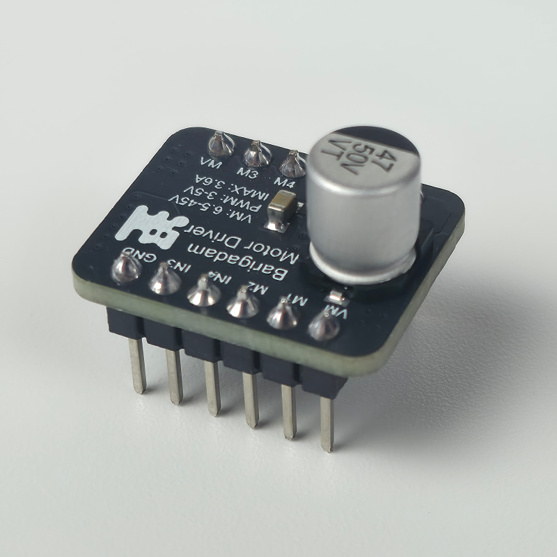
The Motor Driver is an intermediate module between the Control Deck and the motors. It receives a command from Arduino and supplies the required power to the motors. Thanks to this, the program can control the robot's movement: start the motors, change direction, adjust speed, and stop them.
In simple terms, Arduino sends a control signal to the driver, and the driver supplies the motors with power of the required strength and direction.
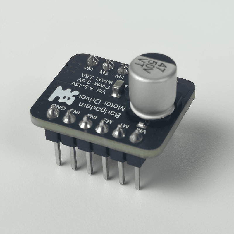
The Barigadam Motor Driver lets you control two DC motors independently.
How a motor is connected
A regular DC motor has two wires. These are power wires: the driver uses them to supply power to the motor. They cannot be connected directly to Arduino digital pins, because the board is not designed for the current required to run a motor.
Both motor wires connect to the two power outputs of one driver channel. On the diagram, these outputs are labeled M1 and M2. The driver itself receives commands from Arduino through two control inputs: IN1 and IN2.
The connection path for one motor can be shown like this:
Arduino → driver inputs IN1 and IN2 → outputs M1 and M2 → motor
The Little Robot uses two motors. When controlled through the library, they correspond to the following numbers and pins:
- motor1 — left wheel, power outputs
M3andM4, control pinsD8andD6; - motor2 — right wheel, power outputs
M1andM2, control pinsD7andD5.
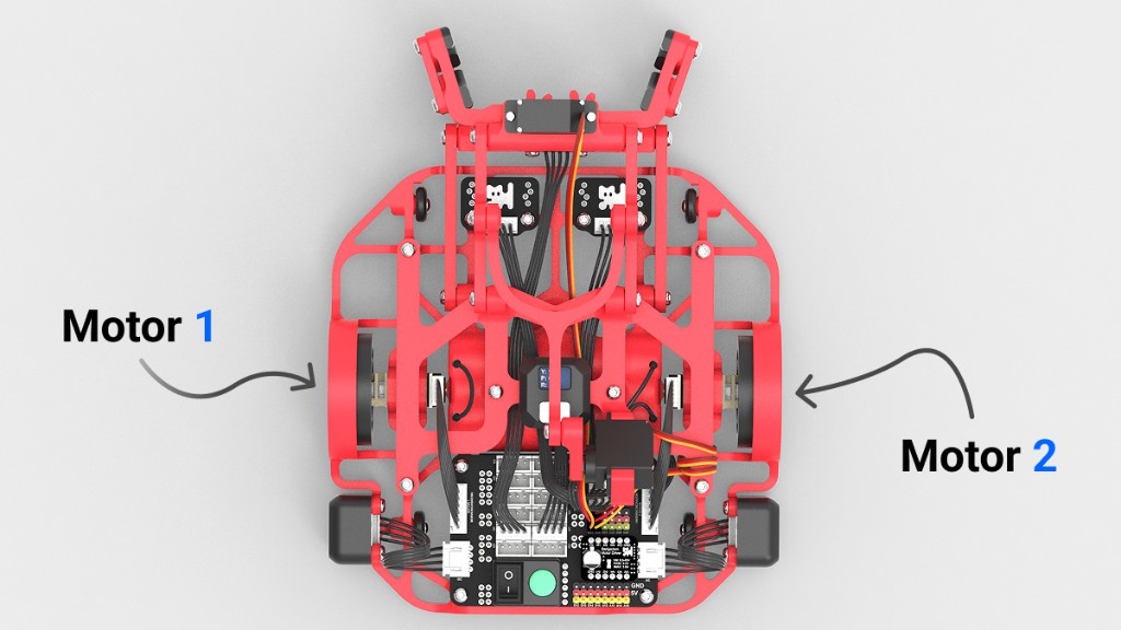
It is important to tell these connections apart. The wires between the driver and the motor carry power, while the pins between Arduino and the driver carry only control signals. Pins D8, D6, D7, and D5 are connected to the driver's control inputs, not directly to the motors.
Why two control pins are needed
The motor's rotation direction depends on which way current flows through it. If you reverse the voltage polarity on the motor wires, it starts rotating in the opposite direction.
Arduino does not physically swap the wires. Instead, it sends signals to the driver's two control inputs. The driver uses these signals to change the voltage polarity on the motor.
The principle can be shown like this:
| First pin | Second pin | Motor action |
|---|---|---|
| Signal | 0 |
Rotation in one direction |
0 |
Signal | Rotation in the opposite direction |
0 |
0 |
Stop |
So one control pin sends a signal for one direction, and the second pin sends a signal for the opposite direction. At the same time as choosing the direction, you can send a PWM signal to the selected pin and change the rotation speed.
If you swap the two power wires on the motor itself, its directions will also swap. That is why the labels "forward" and "backward" depend on how the motor is mounted and connected in the robot.
Controlling a motor with PWM
In the previous lesson, we learned about the analogWrite() command. It creates a PWM signal — it turns a digital pin on and off very quickly. Because of this, the average power that the driver sends to the motor changes: the higher the PWM value, the faster the motor usually rotates.
The command is written like this:
analogWrite(pin_number, pwm_value);
The PWM value is set in the range from 0 to 255:
0— no signal;255— maximum signal;- intermediate values, such as
100or150, set a lower speed.
To control speed, PWM is sent to one of the two control pins, and the other pin is set to 0. The selected pin sets the direction, and the PWM value sets the speed. To change the rotation direction, swap PWM and 0 between the two pins.
Let's look at controlling the left motor without the library:
const int MOTOR_1_D1 = 8;
const int MOTOR_1_D2 = 6;

void setup() {
  pinMode(MOTOR_1_D1, OUTPUT);
  pinMode(MOTOR_1_D2, OUTPUT);

  // rotation in one direction
  analogWrite(MOTOR_1_D1, 120);
  analogWrite(MOTOR_1_D2, 0);
  delay(1000);

  // stop
  analogWrite(MOTOR_1_D1, 0);
  analogWrite(MOTOR_1_D2, 0);
}

void loop() {

}
To run the same motor in the opposite direction, send PWM to the second pin:
analogWrite(MOTOR_1_D1, 0);
analogWrite(MOTOR_1_D2, 120);
The right motor is controlled the same way, but through pins D7 and D5. You can control the motors directly, but in every program you would have to remember the pin numbers, choose the direction yourself, and stop each channel separately. That is why we will use the LittleRobot.h library next — it performs these actions inside a ready-made command.
Control through the LittleRobot library
The LittleRobot.h library simplifies robot control. It hides the work with individual pins and PWM signals, so instead of several analogWrite() commands you can use one ready-made function.
At the beginning of the program, include the library and create a robot object:
#include <LittleRobot.h>

LittleRobot robot;
Inside setup(), perform the initial robot setup:
robot.begin(true, true);
The robot.begin() function prepares the library and the robot's main components for work. It configures the motor pins, the built-in button and LED, starts the encoders, and prepares the I²C interface for sensors. That is why it must be called once at the beginning of the program before using the library commands.
The two true values are not related to motor speed or rotation direction. They set whether the count direction is reversed for the first and second encoders. In this lesson, the standard form robot.begin(true, true) is enough. We will look at the effect of these parameters in detail in the next lesson, when we start reading encoder values.
Before movement starts, it is convenient to add a wait for the button press:
robot.waitButtonPressRelease();
The program stops on this line and continues only after the button is pressed and released. This way, the robot does not start moving immediately after the program is uploaded.
Main motor parameters
To control a motor, the library needs two values: motor number and speed.
We covered motor numbers above. Now let's look at speed.
In this lesson, “speed” is a power command on a −100…100 scale, not a measured wheel speed. Its sign sets direction and its magnitude sets PWM intensity:
- a positive value — rotation in one direction;
- a negative value — rotation in the opposite direction;
0withMotorPower— power is removed; the wheel may coast.
For example, values 40 and -40 set power commands of equal magnitude in opposite directions. For the first tests, it is better to use values 30-50, so the robot does not move too sharply.
Moving with one motor
To control one motor, use this command:
robot.MotorPower(motor_number, speed);
The first parameter is the motor number, and the second is a power command whose sign sets direction.
When working through the LittleRobot library, you do not need to set PWM yourself in the range from 0 to 255. Specify the command magnitude on a 0–100 scale; the library converts it into the internal PWM range.
For a nonzero command, power 1 corresponds to PWM around 20, and 100 to the maximum 255. With MotorPower(..., 0) motor power is removed; the wheel may keep coasting briefly.
For example:
robot.MotorPower(1, 40);
This command starts the left motor with power 40 on the library’s relative scale.
The command remains in effect until another command replaces it. Set 0 to remove power:
robot.MotorPower(1, 0);
Coasting and braking
| Command | What happens when stopping |
|---|---|
robot.MotorPower(1, 0) |
Releases the motor; the wheel may coast |
robot.MotorStart(1, 0) |
Electrically brakes one motor |
robot.MotorsBrake() |
Electrically brakes both motors |
Both MotorPower and MotorStart can start a motor. They control the driver differently; they do not set different maximum speeds. Electrical braking does not correct encoder position: MotorsHold is a separate topic in Lesson 5.
Exercise: run the motor twice at the same low power for the same time. End the first run with MotorPower(1, 0) and the second with MotorStart(1, 0). Compare coasting on the same surface.
Moving with two motors
To make the robot drive forward, start both motors with the same speed.
robot.MotorPower(1, 40);
robot.MotorPower(2, 40);
delay(1000);
robot.MotorPower(1, 0);
robot.MotorPower(2, 0);
The first two lines start the left and right motors. delay(1000) keeps them powered for one second, then the last two lines remove power. The wheels may coast before stopping.
The backward movement algorithm works in the same way, but the speed uses the opposite sign.
robot.MotorPower(1, -40);
robot.MotorPower(2, -40);
delay(1000);
robot.MotorPower(1, 0);
robot.MotorPower(2, 0);
Here both motors rotate in the opposite direction, so the robot drives backward.
Turning with two motors
The robot turns when the wheels rotate differently.
If one motor works faster than the other, the robot will turn smoothly. For example, to make a smooth right turn, the left motor can be made faster than the right motor:
robot.MotorPower(1, 50);
robot.MotorPower(2, 20);
delay(1000);
robot.MotorPower(1, 0);
robot.MotorPower(2, 0);
If you need the robot to turn in place, you can start the motors in opposite directions:
robot.MotorPower(1, 40);
robot.MotorPower(2, -40);
delay(600);
robot.MotorPower(1, 0);
robot.MotorPower(2, 0);
The delay time determines how long the motors rotate in opposite directions. The longer the delay, the more the robot will turn.
With this method, the turn angle is approximate. It is affected by battery charge, the surface, and wheel grip. More precise movement using encoders will be covered in the next lesson.
Stop function
In programs with motors, you often need to stop both motors at once. To avoid writing two identical lines every time, you can create a separate function.
void stopMotors() {
  robot.MotorPower(1, 0);
  robot.MotorPower(2, 0);
}
Now, to stop the robot, it is enough to call:
stopMotors();
This simplifies the code. stopMotors() removes power from both motors; it does not guarantee an instant stop or an exact wheel position.
Practice
Now let's combine the commands we learned into one program. The robot will wait for the button press, drive forward, stop, and turn in place.
#include <LittleRobot.h>

LittleRobot robot;

const int moveSpeed = 40;
const int moveTime = 1000;
const int turnTime = 600;

void stopMotors() {
  robot.MotorPower(1, 0);
  robot.MotorPower(2, 0);
}

void setup() {
  robot.begin(true, true);
  robot.waitButtonPressRelease();

  // drive forward
  robot.MotorPower(1, moveSpeed);
  robot.MotorPower(2, moveSpeed);
  delay(moveTime);
  stopMotors();

  delay(500);

  // turn in place
  robot.MotorPower(1, moveSpeed);
  robot.MotorPower(2, -moveSpeed);
  delay(turnTime);
  stopMotors();
}

void loop() {

}
Let's go through the program step by step:
- The library is included and a
robotobject is created. - Constants store the speed, movement time, and turn time.
stopMotors()removes power from both motors, allowing them to coast.- In
setup(), the robot is configured and waits for the button press. - Both motors start with the same speed, so the robot drives straight.
- After stopping, the motors start in opposite directions, and the robot turns in place.
Change the values of moveSpeed, moveTime, and turnTime and see how they affect the movement. Then extend the program so that after the turn the robot drives forward again.