What is the Control Deck
Now let's move on to the main components that make up the robot. We will start with its most important part: the Control Deck.
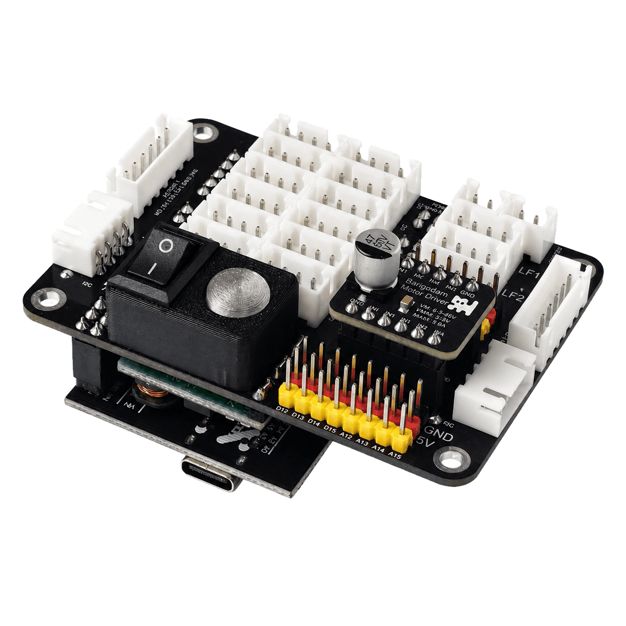
The Control Deck is the central electronic part of the robot. In the Barigadam robot, it is based on the Arduino Mega 2560 Pro and is used to conveniently connect other modules to Arduino: motors, sensors, servos, a button, power, and additional devices.
Connectors and labels on the board
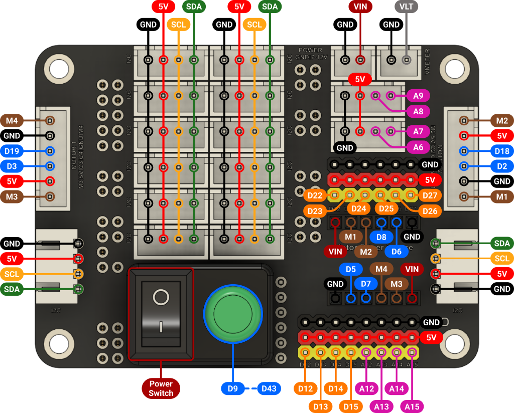
The Control Deck has several main connectors. Power, sensors, motors, and other devices are connected to the board through these connectors.
| Connector on the board | What connects here | Simple explanation |
|---|---|---|
VIN |
Board power | Main power is supplied here. The diagram shows that the power should be 7-12 V. |
5V |
Power for sensors and modules | This contact provides 5 V power. Sensors, servos, and other small devices use it. |
GND |
Common minus | This is ground. Almost every connected device must have a connection to GND. |
SDA and SCL |
I2C sensors and modules | These contacts are used for devices that communicate with the board through I2C, for example sensors or a display. |
D22 - D27 |
Servos | Servos can be connected to these connectors. A servo receives power and a control signal. |
A6 - A9 |
Line sensors | These inputs are used for line sensors. They read a value and send it to the board. |
M1 - M4 |
Motors | The robot motors connect here. Each motor connects to its own connector. |
D2, D3, D18, D19 |
Encoders | Encoders help the board understand how the motors rotate. This is needed for more accurate movement. |
D12 - D15 |
Additional digital pins | Simple devices can be connected here: buttons, LEDs, or digital sensors. |
A12 - A15 |
Additional analog pins | Analog sensors can be connected here. They send not just on/off, but a numeric value. |
D9 |
Robot button | The built-in button is connected to this digital pin. It can be used to start a program or select an operating mode. |
D43 |
Board LED | The built-in LED is connected to this digital pin. The program can turn it on and off. |
VLT |
Voltmeter input | Used to measure voltage. This can be useful for monitoring power. |
Power Switch |
Power switch | Turns the robot power on and off without disconnecting batteries or wires. |
How not to get confused when connecting modules
Each module usually has several wires. Most often these are:
5V— power;GND— ground;- one or more signal wires.
For example, if you connect an I2C sensor, such as a color sensor or a motion sensor, it will usually have 5V, GND, SDA, and SCL contacts. They are connected using a special cable with a suitable connector.
If you connect a servo, it will have power, ground, and a signal wire connected to one of the pins D22 - D27. By looking at the port diagram, you can find the special area for connecting servos.
The main rule: before connecting anything, always check the labels on the board and on the module itself. It is especially important not to mix up 5V and GND, because incorrect power connection can damage the device.
Review the instructions and check the sensor connections. Also check that the batteries are installed correctly. After that, you can turn on the robot.
Digital and analog ports
The Control Deck has different ports for connecting modules. With them, the board can interact with connected devices: send signals or receive signals from sensors. The two main types of ports are digital and analog.
Digital port
Digital ports are labeled with the letter D and a number, for example D9.
A digital port works with only two states: signal present or signal absent. In code, these states are called:
HIGH— high signal level, logical1;LOW— low signal level, logical0.
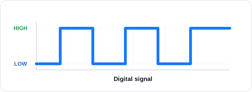
In simple words, a digital port is similar to a switch. It can be either on or off. For example, a digital port can turn on an LED, send a signal to a module, or read the state of a button.
Before using a digital port in a program, you need to specify how it will work: send a signal or receive one.
This is done with the command:
pinMode(pin_number, mode);
For example:
pinMode(9, INPUT);   // input mode
pinMode(9, OUTPUT);  // output mode
The first argument of the function is the port number D9, and the second argument selects the operating mode:
INPUT— the digital port is used to read a signal, for example from a button or sensor;OUTPUT— the digital port is used as an output, meaning it sends a signal to a connected device.
Each mode uses its own commands.
If the port is configured as an input, meaning we want to receive information from a button or sensor, the command digitalRead() is used:
int buttonState = digitalRead(9);
This command reads the signal from port D9 and saves it into the variable buttonState. The variable will contain one of two values: HIGH (1) or LOW (0).
After that, the program can use this value, for example in a condition:
if (buttonState == HIGH) {
  Serial.println("Signal detected");
}
This way Arduino can not only receive a signal, but also make a decision based on its value.
If the port is configured as an output and you need to send a signal to a digital port, use the command:
digitalWrite(pin_number, value);
For example:
digitalWrite(9, HIGH);
delay(500);
digitalWrite(9, LOW);
This block sends a high signal to port D9, waits 500 milliseconds, and returns the signal to a low level. If an LED is connected to this port, it will turn on for half a second and then turn off.
Analog port
Analog ports are labeled with the letter A and a number, for example A0.
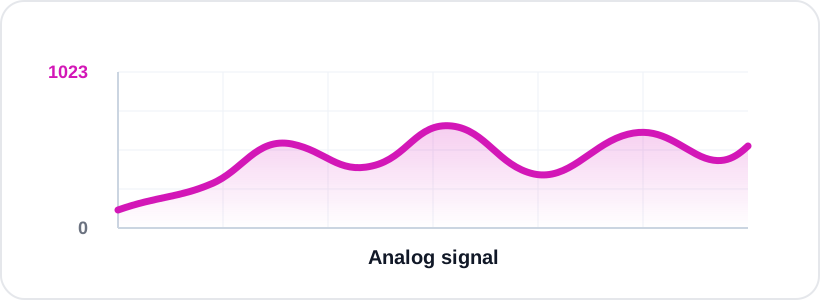
An analog port is used to read values that can change smoothly. Unlike a digital port, there are not only two states here. The value can be small, medium, or large.
For example, an analog port can be used to connect sensors that measure not just "yes" or "no", but some value within a certain range.
Arduino converts an analog signal into a number. Usually this number is in the range from 0 to 1023, where:
0— minimum value;1023— maximum value;- values between them show an intermediate signal level.
To read an analog port, use the command:
analogRead(pin_number);
For example:
int value = analogRead(A0);
This command reads the value from port A0 and saves it into the variable value. For normal analog reading, the command pinMode() is not required. It is enough to use analogRead().
The variable is needed so the program can use the received number later. For example, it can print the number to Serial Monitor or make a decision using a condition.
Serial.println(value);
This lets you see what values the sensor is producing at the moment.
For example, if a line sensor is connected to an analog port, different surfaces may produce different values. A light surface may produce one value, and a dark surface may produce another. Thanks to this, the robot can understand where the line is.
I2C ports
Besides digital and analog ports, the Control Deck also has I2C ports. They are used to connect more complex modules that do not simply output one signal, but exchange data with the board.
For example, a color sensor, motion sensor, display, and other modules that need to transfer more data can work through I2C.
I2C can be imagined as a shared communication line between Arduino and the connected devices. Through this line, the board can send commands to a module and receive data from it.
Usually an I2C module has four contacts:
5V— module power;GND— ground;SDA— data line;SCL— clock line.
Unlike a digital port, I2C does not work simply as HIGH or LOW. And unlike an analog port, it does not just read one number. Through I2C, the board and the module exchange data according to certain rules.
To work with I2C in Arduino, the library is used:
#include <Wire.h>
It handles the data exchange over I2C itself. But for Barigadam sensors, the Wire.h library alone is not enough, because the special sensor commands are stored in separate libraries.
For example, the color sensor uses this library:
#include <Barigadam_ColorSensor.h>
And the motion sensor uses this one:
#include <Barigadam_MotionSensor.h>
Without the required library, the program will not know the sensor commands. Both libraries use objects: BarigadamColorSensor for color and BarigadamMotionSensor for motion. Each object stores one sensor’s I²C address; call its methods using a dot.
That is why at the beginning of the program you usually include Wire.h and the library for the sensor you need:
#include <Wire.h>
#include <Barigadam_ColorSensor.h>
With both libraries included, declare the two different modules like this:
BarigadamColorSensor colorSensor(0x40);
BarigadamMotionSensor motionSensor(0x60);
These are the library defaults. Declaring an object does not reprogram a device address. Check the actual address with a scanner.
I2C device addresses
The main feature of I2C is that several devices can be connected to the same line. So that the board understands which module it is working with, each I2C device has its own address.
An address is like an apartment number. All devices are connected to the same communication line, but Arduino talks to a specific module by its address.
I2C addresses are usually written in hexadecimal form. For example:
0x40
The prefix 0x shows that the number is written in hexadecimal. For now, it is not important to calculate such numbers manually. It is important to understand that this is the address of a specific device.
For example, if two sensors are connected to one I2C line, they must have different addresses:
0x40
0x41
If two devices have the same address, the board will not be able to correctly understand which device it is talking to. That is why identical I2C devices sometimes need to be configured with different addresses.
Important note: for Barigadam sensors, the I2C address can be selected in the range from 0x40 to 0x60. For example, you can use addresses 0x40, 0x41, 0x42, and so on up to 0x60.
Finding and changing an address
Each I2C device has its own address. Arduino uses this address to understand which module it needs to exchange data with. The address may be written in the module documentation, but it can also be found using a special program: an I2C scanner.
An I2C scanner checks possible addresses and prints found devices to Serial Monitor. The current motion-sensor library provides this static method:
BarigadamMotionSensor::scanI2C();
It is used by File → Examples → Barigadam_MotionSensor → I2C_Scan. For color, use BarigadamColorSensor::scanI2C(). Both scanners run forever, scanning every five seconds: code after the call does not run. Call Serial.begin(9600) and Wire.begin() before starting either scanner.
After running the scanner, you can see the address of the connected device in Serial Monitor:

This means that a device with the address 0x60 was found on the I2C line.
Sometimes the device address needs to be changed. This is required when several identical I2C modules are connected to one board. For example, if two sensors have the same address 0x40, Arduino will not be able to distinguish them correctly. So one sensor can keep the address 0x40, and the second one can be assigned another address, for example 0x41.
With the new motion-sensor library, first create an object at the current address:
BarigadamMotionSensor sensor(0x60);
Then call its address-change method:
if (sensor.changeAddress(0x41)) {
  Serial.println(sensor.getAddress(), HEX);
}
Here, 0x60 is the current address found by the scanner and 0x41 is the chosen unused new address. The valid range is 0x40–0x60; the new address must differ from the current one. After success, sensor automatically uses the new address. This deliberately reconfigures the module: subsequent sketches and LittleRobot settings must use its actual address. The bundled MotionSensor ChangeAddress example instead demonstrates 0x60 → 0x40.
The motion-sensor address-change sequence is:
- Connect only one sensor whose address will be changed.
- Open
Barigadam_MotionSensor → ChangeAddressand set the current and new addresses. - Upload the sketch and check its Serial Monitor result.
- Run
I2C_Scanand verify that the new address is found.
It is important to change the address of only one connected sensor at a time. If two identical sensors with the same address are connected at once, the board will not understand which sensor should receive the command.
The color sensor follows the same principle: create BarigadamColorSensor with its current address and call sensor.changeAddress(new_address). After a successful change the object continues using the new address. The range is also 0x40–0x60; keep only the sensor being configured connected.
Try to identify the addresses of connected I2C sensors with the matching scanner. If several modules share one bus, configure a unique address for each device.